Industrial metalworking and fabrication consistently present operators with a highly specific geometric challenge. Achieving high material removal rates inside confined spaces, deep cylinders, or complex angles is incredibly difficult when standard right-angle tools simply cannot fit. Operators frequently encounter internal welds, deep casting channels, and narrow pipe interiors that demand aggressive grinding, yet remain entirely inaccessible to conventional equipment.
Relying on the wrong tool for these tasks creates massive operational bottlenecks. Angle grinders lack the necessary physical clearance for internal pipe work due to their perpendicular gear housings. Standard die grinders, while compact, lack the sustained torque required for heavy weld removal or thick mill scale. This mismatch forces operators to use undersized tools, leading to drastically increased labor time, rapid consumable wear, stalled motors, and highly inconsistent surface finishes.
The Straight Grinder is the purpose-built solution engineered specifically for linear, high-torque grinding applications. Understanding its internal mechanics, power configurations, and specific application strengths is critical for procurement teams and shop managers looking to optimize tooling ROI and operator safety.
Linear Power Transfer: A straight grinder aligns the motor and spindle on a single axis, delivering direct, high-torque power transfer ideal for internal grinding and heavy material removal.
Application Specificity: It bridges the gap between the high-speed precision of a die grinder and the aggressive material removal of an angle grinder, specifically excelling in pipe fabrication, foundry work, and deep-bore deburring.
Power Source Trade-offs: Choosing between an electric straight grinder and a pneumatic model dictates shop infrastructure requirements, duty cycle limits, and long-term maintenance costs.
Safety and Compliance: Proper evaluation must account for spindle speed matching, abrasive wheel ratings, pre-operation idle testing, and vibration dampening to mitigate wheel burst risks and operator fatigue.
The Core Mechanics: How a Straight Grinder Operates
Motor and Drive Shaft Alignment
The defining structural characteristic of this tool is the parallel alignment of the motor, drive shaft, and spindle. This linear configuration completely eliminates the need for bevel gears, which are standard in right-angle grinders. Bevel gears redirect mechanical power at a 90-degree angle, inherently causing mechanical energy loss, generating excess heat, and creating a primary point of mechanical failure under heavy vibration. By removing these gears, the linear drive system ensures that maximum motor power transfers directly to the abrasive wheel.
This direct-drive approach minimizes internal wear points and reduces gear maintenance. The bearings sit directly behind the collet or threaded spindle, taking the axial load straight back into the robust outer housing. This makes the tool incredibly rigid. When an operator pushes hard into a steel corner, the linear shaft resists deflection much better than a geared right-angle shaft, providing a slimmer tool profile capable of reaching deep into narrow metal channels without compromising structural integrity.
Torque vs. Speed Dynamics
A strict mechanical relationship exists between rotational speed (RPM) and torque. Linear grinding tools typically operate at lower RPM ranges, generally between 4,000 and 12,000 RPM. In contrast, smaller precision tools spin up to 30,000 RPM. This lower speed prioritizes sustained torque over rapid rotation. High torque prevents the tool from stalling or bogging down under heavy loads during aggressive metal removal.
When an operator applies heavy axial pressure against a thick steel weld, the motor must maintain its rotational force to keep the abrasive cutting. If a tool lacks torque, the abrasive wheel binds in the metal, the RPM drops to zero, and the motor draws massive amperage, which can quickly burn out the windings. Sustained torque ensures the abrasive grains continue to fracture and expose new sharp edges, rather than glazing over and simply rubbing against the workpiece.
Abrasive Interaction and Material Removal Rates (MRR)
The micro-physics of the grinding process dictate overall performance and efficiency on the shop floor. As the abrasive wheel spins and contacts the workpiece, each moving abrasive particle acts as a tiny, single-point cutting tool. These particles shear away microscopic chips of metal. The linear orientation allows operators to apply direct axial pressure in a straight line, maximizing the cutting depth of each abrasive grain.
This geometry enables the use of larger grinding stones, heavy flap wheels, and dense wire brushes to aggressively remove metal without deflecting off the work surface. The result is a significantly higher Material Removal Rate (MRR) in confined spaces compared to any other handheld tool. You can measure MRR by calculating the volume of metal removed per minute, and in deep-bore applications, linear tools consistently outperform right-angle alternatives by a wide margin.
Straight Grinder vs. Alternatives: Defining the Success Criteria
Straight Grinders vs. Angle Grinders
Understanding access and geometry is fundamental when choosing between these two primary fabrication tools. Angle grinders utilize a perpendicular cutting action, requiring wide clearance above the work surface. A linear tool utilizes a parallel action, extending the abrasive straight out from the operator's hands. You need a straight tool for deep internal diameters (ID), narrow structural channels, and enclosed vessels. Angle grinders simply cannot reach inside a six-inch steel pipe to grind a root pass.
Consumable orientation also dictates cutting limitations. Straight tools utilize cylindrical stones, abrasive cones, and radial flap wheels designed for internal shaping, filing, and bore polishing. Angle grinders rely on flat, thin discs. While angle grinders remain the absolute standard for cutting metal and flat surface blending, straight tools are strictly optimized for internal shaping and heavy deburring. Attempting to use a straight tool for standard cut-off operations is highly inefficient and dangerous.
Straight Grinders vs. Die Grinders
Frequent confusion surrounds the scale and material removal capabilities of these tools. Die grinders are high-speed, low-torque tools designed for precision polishing, light deburring, and intricate die maintenance. Straight tools are high-torque, lower-speed workhorses built for heavy structural steel, heavy casting removal, and aggressive weld blending. Using a die grinder to remove thick weld slag will immediately stall the motor and destroy the small abrasive burr.
Tooling differences further separate their applications. Die grinders typically use 1/4-inch or 6mm collets designed to hold small carbide burrs and mounted points. Straight tools often feature robust threaded spindles, such as 5/8"-11, or much larger collet systems. This heavy-duty spindle design accommodates heavier, larger-diameter abrasives needed for serious metal removal, ensuring the shaft does not bend or snap under heavy lateral pressure.
| Tool Type | Typical RPM Range | Primary Application | Spindle/Collet Size | Torque Level |
| Die Grinder | 20,000 - 30,000 | Precision deburring, porting, polishing | 1/4" or 6mm Collet | Low |
| Angle Grinder | 8,000 - 11,000 | Flat surface grinding, metal cutting | 5/8"-11 Thread | Medium to High |
| Straight Grinder | 4,000 - 12,000 | Internal pipe grinding, heavy foundry fettling | 5/8"-11 Thread or Large Collet | Very High |
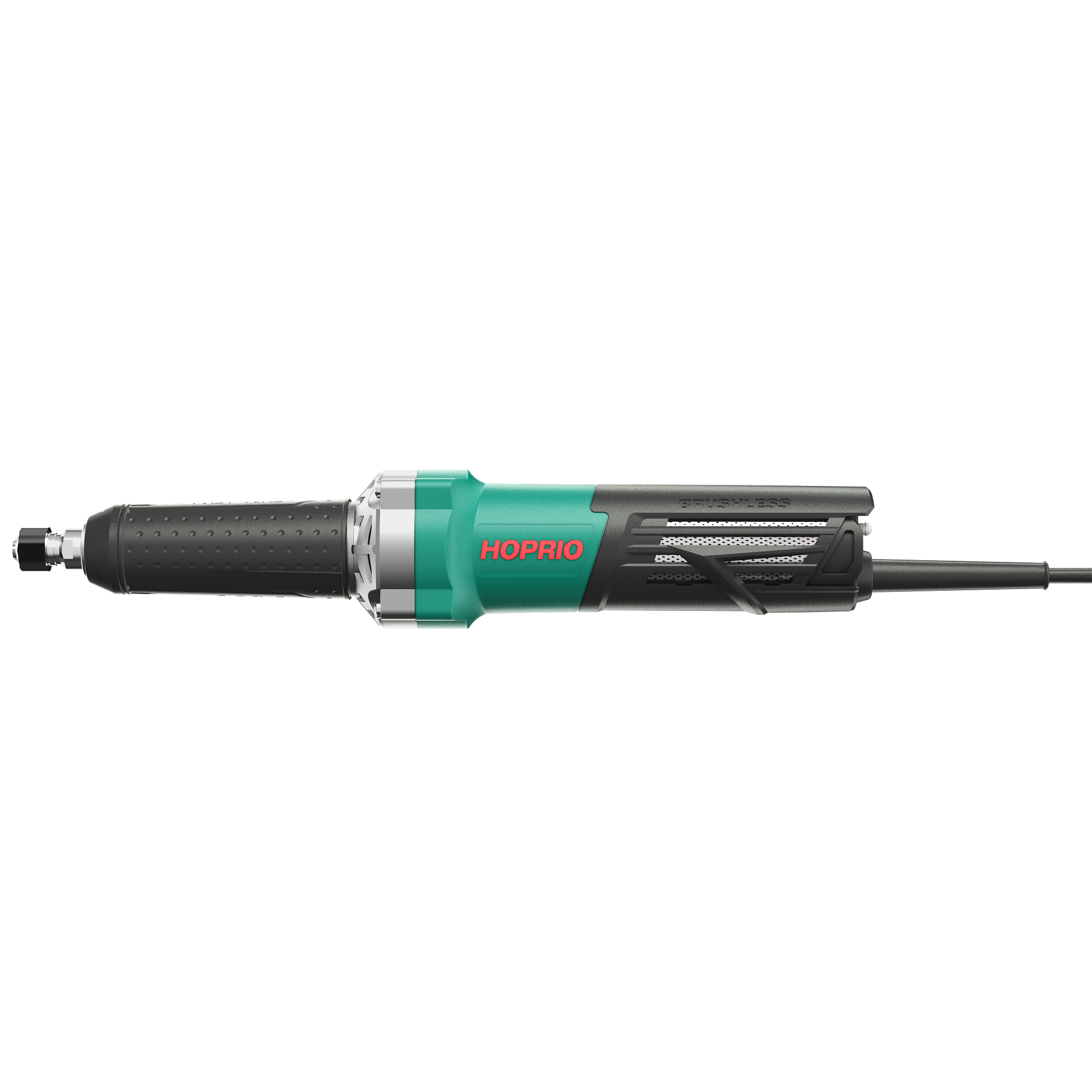
Key Metalworking Applications for Straight Grinders
Internal Cylinder and Pipe Fabrication
Pipeline construction, pressure vessel fabrication, and custom exhaust building rely heavily on linear grinding tools. The extended reach allows operators to grind internal longitudinal and circumferential welds that remain completely inaccessible to right-angle tools. When welding heavy-wall pipe to API standards, the internal root pass often requires smoothing to ensure proper fluid flow and pass non-destructive testing (NDT).
A Handheld Straight Grinder provides the necessary leverage and reach to blend these internal seams seamlessly without gouging the surrounding pipe wall. Operators can plunge a Type 11 cup wheel or a large resinoid cone deep into the pipe, applying heavy pressure to knock down the weld reinforcement quickly. This capability is non-negotiable in the oil and gas sector where internal pipe geometry must be flawless.
Heavy-Duty Deburring, Surface Prep, and Weld Preparation
Structural steel fabrication requires extensive and rigorous surface preparation. Operators use handheld linear grinders to bevel thick metal edges prior to welding, ensuring proper weld penetration. They perform critical surface prep to remove tough mill scale, heavy rust, and old coatings from deep structural channels like I-beams and C-channels where a standard grinding guard gets in the way.
Post-welding, these tools eliminate heavy slag, spatter, and sharp edges efficiently, preparing the metal structure for final painting or powder coating. When fabricating bridge girders or heavy equipment frames, the ability to push a heavy wire wheel into a tight 90-degree inside corner saves hours of manual filing and scraping.
Casting Cleaning and Foundry Applications
Metal casting facilities depend entirely on high-torque linear tools for heavy material removal. The rigorous process of "fettling" involves removing large risers, gates, and parting line flash from heavy iron, steel, or aluminum castings. These excess pieces of metal are often located inside deep cavities or complex casting geometries.
Sustained torque is mandatory for this aggressive application. The tool must power through thick, hardened cast metal without stalling or overheating the motor. Cast iron and ductile iron are notoriously brutal on power tools, generating massive amounts of vibration and heat. A linear tool with a heavy-duty armature and direct drive handles this abuse far better than any geared alternative.
Evaluating Power Sources: Electric Straight Grinder vs. Pneumatic
The Electric Straight Grinder
An Electric Straight Grinder offers consistent, reliable torque under heavy load and operates entirely independent of expensive air compressor infrastructure. You can plug it into standard industrial outlets or portable generators and begin working immediately, making it ideal for field work, remote job sites, and high-elevation structural steel erection where dragging heavy air hoses is a safety hazard.
Modern brushless electric motors provide excellent power efficiency and require less maintenance than older brushed models. However, implementation realities require careful consideration. Electric models carry heavier tool weight due to the dense copper motor windings and internal electronics. They are highly susceptible to conductive metallic dust, requiring epoxy-coated armatures and sealed bearings for longevity in fabrication shops. Operators must also monitor for potential thermal overload during continuous, heavy-duty cycles.
Pneumatic (Air-Powered) Straight Grinders
Pneumatic models boast a vastly superior power-to-weight ratio because they lack heavy copper windings. Air motors run much cooler than electric counterparts because the expanding exhaust air actively cools the internal mechanisms. This thermal advantage allows for 100% duty cycles in high-volume, continuous production environments like foundries and heavy manufacturing plants. Operators experience less fatigue due to the lighter weight.
Despite the performance benefits, hidden infrastructure requirements complicate pneumatic adoption. They require high-capacity rotary screw air compressors, extensive rigid piping, and inline oilers to function correctly. Compressed air systems are notoriously energy inefficient compared to direct electric power, often experiencing line pressure drops that negatively impact tool performance at the end of a long air hose. Moisture in the air lines can also cause internal rusting if the system lacks proper desiccant dryers.
Technical Evaluation Dimensions for Procurement
RPM and Spindle Specifications
Matching tool RPM to the intended abrasive is a non-negotiable safety requirement. Selecting a grinder with an RPM that exceeds the maximum safe speed of the grinding stone is a critical safety failure that leads to catastrophic wheel bursts. Always verify the spindle thread size and the maximum rated RPM before mounting any accessory.
Procurement teams must ensure that the tools purchased align perfectly with the speed ratings of the abrasives already stocked in the tool crib. You must also consider Surface Feet Per Minute (SFPM). A large diameter wheel spinning at 8,000 RPM has a much higher surface speed than a small diameter wheel at the same RPM. The tool's speed must match the optimal cutting speed of the specific abrasive grain being used.
Material-Specific Abrasive Selection
The workpiece material dictates the abrasive choice and the required tool specifications. Grinding mild steel requires different abrasives compared to stainless steel or aluminum. Aluminum is soft and gummy, often requiring specialized wheels or wax lubricants to prevent the abrasive from loading and glazing over.
Aluminum Oxide: The standard choice for grinding carbon steel and general ironwork. It fractures well under heavy pressure to keep cutting.
Zirconia Alumina: Excellent for stainless steel and high-tensile alloys. It holds up better under high heat and aggressive grinding.
Ceramic Alumina: Provides the absolute highest material removal rates on hardened steel and armor plate, though it requires significant downward pressure to function correctly.
Silicon Carbide: The go-to abrasive for non-ferrous metals like aluminum, brass, and titanium, preventing the wheel from loading up with soft metal shavings.
Ergonomics and Operator Control
Modern grinder design prioritizes safety, control, and long-term operator comfort. Paddle switches with safety lock-offs (dead-man switches) prevent accidental starts if the tool is dropped. Extended housings allow for secure two-handed control, providing the leverage needed to fight rotational torque when plunging into a pipe.
Anti-vibration side handles and internal dampening systems are crucial to reduce Hand-Arm Vibration Syndrome (HAVS) during prolonged use. HAVS causes permanent nerve and joint damage, often referred to as "white finger." Tools equipped with auto-balancing flanges and rubberized grip zones significantly reduce the vibration transferred to the operator's hands, extending safe working times.
Consumable Compatibility and Inventory Management
The choice of spindle size directly impacts consumable availability and shop floor efficiency. Standardizing tool spindles across a facility reduces abrasive inventory complexity. Keeping a unified spindle size means fewer mismatched wheels, streamlined procurement processes, and less confusion for operators.
When all linear grinders in a shop accept the same 5/8"-11 threaded cones and plugs, you eliminate the risk of operators attempting to modify incompatible abrasives to fit the wrong tool. This standardization prevents dangerous field modifications, such as drilling out the arbor hole of a grinding stone, which destroys the structural integrity of the wheel and guarantees a blowout.
Implementation Risks and Safety Compliance
Mitigating Wheel Burst Risks
A wheel burst caused by over-speeding, physical damage, or improper mounting is a catastrophic event that sends high-velocity shrapnel across the shop floor. Mandatory safety checks are vital. Operators must follow a strict protocol before pulling the trigger on a new wheel.
Inspect the wheel visually for any chips, cracks, or signs of chemical degradation.
Perform the "Ring Test" for vitrified wheels by tapping the wheel gently with a non-metallic handle. Listen for a clear ring; a dull thud indicates a hidden internal crack.
Verify the RPM rating printed on the wheel's blotter is equal to or greater than the tool's maximum free-speed RPM.
Ensure proper protective cover placement and use the correct mounting flanges without over-tightening the arbor nut.
Conduct a mandatory 30-second idle run test in a safe direction, away from personnel, before applying the tool to the workpiece.
Managing Operator Fatigue and Kickback
Operating high-torque linear grinders demands physical stamina and strict situational awareness. Kickback can occur violently if the grinding wheel binds in a tight corner, catches on a jagged metal edge, or drops into a gap in the workpiece. Mitigation strategies include maintaining a proper, balanced stance with feet shoulder-width apart and keeping the tool below shoulder height.
Operators must understand the rotational pull of the tool to anticipate sudden movements. Utilize comprehensive Personal Protective Equipment (PPE), including heavy leather gauntlets, a full face shield worn over safety glasses, and flame-resistant clothing. Implement mandatory rest cycles or provide vibration-dampening gloves to manage fatigue during heavy grinding shifts, ensuring operators maintain a firm, controlled grip at all times.
Conclusion
Audit your current fabrication floor to identify specific bottlenecks in internal pipe grinding, weld preparation, or casting fettling where right-angle tools are failing.
Standardize your abrasive inventory by matching spindle thread sizes across all heavy-duty grinding tools to prevent dangerous field modifications.
Implement a mandatory daily ring test and 30-second idle-run protocol for all operators before they begin any metal removal tasks.
Schedule an on-site demonstration to test tool ergonomics, vibration levels, and actual material removal rates under your specific shop conditions.
FAQ
Q: What is the difference between a straight grinder and a die grinder?
A: A die grinder is a high-speed, low-torque tool designed for precision polishing and light deburring using small collets. A straight grinder is a lower-speed, high-torque tool built for aggressive material removal, heavy weld blending, and casting cleaning using larger threaded spindles.
Q: Can you use an electric straight grinder for cutting metal?
A: No. Straight grinders are optimized for internal shaping, grinding, and deburring using cylindrical stones or flap wheels. They are not designed for standard cut-off operations. Angle grinders are the correct tool for cutting metal with flat abrasive discs.
Q: What are the most common abrasives used on a handheld straight grinder?
A: Common abrasives include cylindrical grinding stones, abrasive cones, radial flap wheels, and heavy-duty wire brushes. These accessories are specifically shaped to handle internal diameters, deep channels, and heavy surface preparation tasks.
Q: How do you determine the correct RPM for a straight grinder wheel?
A: Always check the manufacturer's label on the abrasive wheel. The maximum safe RPM rating printed on the wheel must be equal to or greater than the maximum free-speed RPM of the grinder. Never mount a wheel rated for a lower speed.
Q: Why choose a pneumatic straight grinder over an electric one?
A: Pneumatic straight grinders offer a superior power-to-weight ratio and run cooler, allowing for 100% duty cycles in continuous production environments like foundries. However, they require expensive air compressor infrastructure and inline oilers to operate effectively.
Q: What safety gear and pre-checks are required when operating a straight grinder in metalworking?
A: Operators must wear heavy gauntlets, a face shield, safety glasses, and hearing protection. Pre-checks include verifying RPM ratings, performing a "Ring Test" on vitrified wheels, ensuring guards are secure, and running a 30-second idle test in a safe direction.


