
Views: 0 Author: Site Editor Publish Time: 2026-10-28 Origin: Site


Modern brushless motors deliver exceptional efficiency and compact power. They are favored across heavy industries and consumer electronics alike. But a critical engineering question arises. How do they actually start without physical sensors? A stationary rotor produces zero Back-EMF signals. This physical reality makes the initial startup phase incredibly complex. In this comprehensive guide, we will break down the exact sequence a sensorless system uses to force a motor to start. We will explore the advanced algorithms operating behind the scenes and share practical troubleshooting steps for common field hurdles.
A sensorless system relies on Back-Electromotive Force, commonly known as Back-EMF, to determine the exact position of the rotor. However, this signal is completely non-existent at zero speed.
To initiate rotation, the hardware executes a highly specific three-step open-loop sequence. This includes Rotor Alignment, Open-Loop Ramp-Up, and the Switchover to Closed-Loop control.
Sensorless architectures completely eliminate the need for physical sensors. This design choice reduces wiring complexity, lowers manufacturing costs, and significantly increases mechanical reliability in harsh environments.
Selecting the appropriate hardware requires engineers to carefully balance startup load requirements, operational speed ranges, and extreme environmental conditions.
To fully grasp the complexities of the startup sequence, we must first establish the foundational mechanics of how these electronic systems operate during normal rotation.
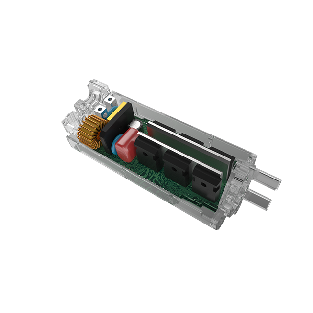
A bldc controller is a sophisticated electronic device responsible for directing electrical current to the correct motor phases. It does this at the precise moment required to sustain rotation. Unlike traditional brushed motors relying on mechanical commutators, brushless DC motors require electronic commutation. The control board acts as the central brain. It rapidly switches power transistors, usually MOSFETs or IGBTs, on and off to create a rotating magnetic field within the stator. The permanent magnets embedded on the rotor naturally chase this shifting magnetic field. This continuous chasing creates torque and rotational movement.
In a conventional setup, physical sensors detect the magnetic poles of the rotor. This tells the microprocessor exactly when to switch the current. A sensorless system removes these physical components. Instead, it relies on a phenomenon known as Back-EMF.
According to Faraday’s Law of Induction, as permanent magnets spin past the copper coils of the stator, they generate a voltage. This voltage pushes back against the driving voltage. The system monitors the un-driven phase of the motor to read this Back-EMF voltage. By analyzing the timing of this electrical feedback, the microprocessor can accurately calculate the rotor position and speed in real-time. It completely bypasses the need for physical positioning hardware.
While Back-EMF provides an elegant solution for running a motor at high speeds, it introduces a massive engineering hurdle during the initial startup phase.
The fundamental physics of electromagnetism dictate that Back-EMF is directly proportional to rotational speed. When the motor spins rapidly, the signal is robust and clear. An Analog-to-Digital Converter can interpret it easily. If you probe the phase lines with an oscilloscope at high speeds, you will see a distinct waveform.
However, at a dead stop, the magnetic field is not moving relative to the stator coils. Consequently, the Back-EMF is exactly zero. Without this crucial signal, the system is effectively blind. It possesses no data regarding the current resting angle of the rotor. This makes it mathematically impossible to apply the correct commutation sequence for maximum starting torque.
If the hardware simply applies power to random phases without knowing the orientation of the rotor, the results are highly unpredictable. The magnetic field generated by the stator might push against the rotor in the wrong direction.
This blind commutation causes the motor to violently jitter in place. It might emit a high-pitched whine, spin backward temporarily, or stall completely. Furthermore, applying continuous power to a stalled motor causes a massive spike in electrical current. This thermal overload can quickly melt stator windings or permanently destroy the MOSFETs on the circuit board. To prevent catastrophic failure, engineers developed a precise forced startup sequence.
To overcome the zero-speed limitation, a motor driver utilizes a forced open-loop sequence. This methodology temporarily ignores the lack of feedback. It forces the motor to spin until it generates enough momentum to be measured.
The microprocessor lacks initial position data. Therefore, it must force the rotor into a predictable starting position. During the alignment phase, the hardware injects a steady direct current through two specific motor phases. The third phase remains open.
This action creates a strong stationary magnetic field within the stator. The permanent magnets on the rotor are forcibly pulled toward this field until they align perfectly. The system holds this current for a fraction of a second. This ensures any residual mechanical oscillations dampen out completely. By the end of this step, the exact position of the rotor is locked in.
Once the rotor is securely aligned, the ramp-up phase begins. The motor is still not spinning fast enough to generate a readable Back-EMF signal. Thus, the system must operate entirely in open-loop mode.
During this critical window, the driver forcefully steps the magnetic field forward at a progressively increasing rate. It treats the brushless motor like a standard stepper motor. It blindly sends a sequence of electrical pulses, assuming the inertia of the rotor will allow it to follow the rotating magnetic field. The acceleration rate must be meticulously tuned in the firmware. If the magnetic field accelerates too aggressively, the rotor loses synchronization and stalls. Conversely, if it accelerates too slowly, the motor draws excessive current.
As the open-loop acceleration forces the rotor to spin faster, the motor begins acting like a generator. The pivotal moment occurs when the motor reaches a minimum threshold speed. This is typically between five and ten percent of its maximum rated RPM.
At this velocity, the Back-EMF signal becomes strong enough to pierce through ambient electrical noise. The microprocessors detect this clean signal and instantly abandon the blind open-loop sequence. The architecture seamlessly transitions over to closed-loop control. From this point forward, real-time Back-EMF feedback times the phase switching perfectly. This ensures maximum operational efficiency and torque delivery.
Looking at the broader industrial landscape, there is a massive migration toward sensorless architectures. Sectors like automotive thermal management, consumer appliances, and industrial fluid control are actively phasing out legacy systems. As digital signal processors and microcontrollers become cheaper and computationally more powerful, advanced sensorless algorithms are trickling down to everyday electronics. Market data indicates that the demand for sensorless solutions is surging because manufacturers are prioritizing supply chain simplification. Fewer physical components mean fewer points of failure, lower raw material costs, and streamlined assembly lines. This shift fundamentally changes how engineers approach high-speed rotating equipment design.
Engineers must frequently decide between sensored and sensorless architectures during the prototyping phase. The optimal choice depends entirely on the mechanical load profile and the intended operating environment.
Sensored systems excel in applications demanding massive breakaway torque from a dead stop. Electric bicycles, robotic arms, and heavy-duty traction vehicles rely heavily on this architecture. A physical hall sensor tells the microprocessor exactly where the rotor is at all times. This ensures a perfectly smooth startup under heavy loads. However, these physical sensors are often the weakest link in the chain. They are highly vulnerable to failure under extreme temperatures or intense mechanical vibration.
In contrast, the sensorless approach prioritizes rugged durability and high-speed efficiency. By stripping away the physical sensors, the motor becomes practically immune to environmental hazards like extreme heat, moisture, and dust ingress. This makes sensorless control the undisputed standard for drones, HVAC blowers, and submersible industrial pumps.
| Feature | Sensored Controller | Sensorless Controller |
|---|---|---|
| Startup Torque | Extremely High | Low to Moderate |
| Low-Speed Operation | Smooth and precise | Prone to jittering |
| High-Speed Efficiency | Good | Exceptional |
| Environmental Durability | Vulnerable to heat and dust | Highly robust |
| Wiring Complexity | High | Minimal |
Understanding the physical startup sequence is only one piece of the puzzle. The true intelligence of a brushless controller lies in its firmware. Depending on performance requirements, different mathematical algorithms are deployed to handle the transition from open-loop startup to closed-loop operation.
Zero-crossing detection is the most traditional algorithm for sensorless commutation. It is often referred to as trapezoidal or six-step control. In a standard three-phase motor, two phases are energized at any given time. The third phase is left floating. As the magnetic rotor sweeps past these stator coils, it induces a voltage in the floating phase. An internal comparator circuit monitors this voltage. When the Back-EMF exactly equals half of the DC bus voltage, a zero-crossing event registers. The algorithm calculates the time between these events to determine rotor speed. While highly reliable at cruising speeds, this method fundamentally fails at zero speed.
For applications requiring buttery-smooth operation and lower acoustic noise, Field-Oriented Control is the premier algorithm. Unlike rigid trapezoidal control, Field-Oriented Control drives all three phases simultaneously with continuous sinusoidal currents. The firmware utilizes advanced mathematical transformations to convert a complex three-phase AC system into a simpler two-coordinate system. Sophisticated software models estimate the rotor position by analyzing phase voltages and currents. This provides superior dynamic response but requires robust processing power.
The most significant limitation of standard sensorless control is the inability to determine rotor position at a complete standstill. High-Frequency Injection is a cutting-edge algorithmic solution engineered to solve this exact problem without physically moving the rotor. It exploits the magnetic saliency of the motor. Before startup, the system injects a low-voltage high-frequency signal into the stator windings. By measuring the resulting current ripple, the algorithm mathematically deduces the exact position of the magnetic poles. This allows maximum torque application from zero RPM.
Prototyping a sensorless system involves rigorous bench testing. Because the initial startup relies on blind timing, environmental variables and sudden load changes easily disrupt the process. Below are the most common issues field engineers encounter and actionable technical solutions.
During bench testing, the motor might vigorously shake back and forth but fail to rotate continuously. This means the rotor alignment phase is likely failing. It is typically caused by incorrect alignment parameters. If the alignment current is too weak, it cannot overcome mechanical static friction to pull the rotor into position. Engineers should access the firmware parameters to incrementally increase the alignment current and extend the duration by fifty to one hundred milliseconds.
Occasionally, a motor briefly spins backward before catching the forward sequence. This occurs when the open-loop commutation sequence is out of sync with the actual physical inertia of the rotor. If the magnetic field rotates faster than the rotor can physically follow, the fields slip. The solution is to decrease the open-loop acceleration rate. A slower ramp-up allows the physical mass of the rotor to stay locked with the rotating stator field.
Sensorless systems notoriously struggle against heavy initial loads. If the motor starts flawlessly unloaded but stalls when attached to a mechanical assembly, the open-loop torque is insufficient. The inertia of the load prevents the motor from reaching the minimum RPM required to generate a readable signal. Verify that the hardware is rated to deliver the necessary peak startup current. If adjusting firmware parameters fails, transitioning to a sensored architecture may be the only physically viable engineering solution.
Selecting the correct architecture is a critical procurement decision. It directly impacts product performance, longevity, and overall safety. Engineers must evaluate several technical parameters before finalizing their hardware selection.
The first step is a rigorous mechanical assessment of the target system. Calculate the breakaway torque required to initiate movement and evaluate the total system inertia. If the application involves high static friction, such as a loaded winch, a standard sensorless system will likely fail. Conversely, for low-inertia applications like fan blades or centrifugal pumps, sensorless control is the most cost-effective and reliable choice.
Modern hardware offers a vast array of protective features. Technical buyers should look for platforms providing programmable open-loop ramp-up profiles. This allows for fine-tuning based on specific motor inductance. For heavy-duty applications, industrial-grade solutions like the Hoprio HP-DB2203 2000W Big Power Permanent Magnet controller provide the necessary muscle. These units feature robust overcurrent protection, thermal shutdown capabilities, and phase-loss detection. They are engineered to handle wide voltage inputs and deliver high peak currents, ensuring reliable startup even under demanding industrial conditions.
Integrating a motor control system is rarely a simple plug-and-play endeavor. Even premium hardware requires careful firmware tuning to match the specific resistance of your chosen motor. Working with an experienced manufacturer who provides comprehensive engineering support is vital. It reduces time-to-market and ensures flawless operation under demanding conditions.
Starting a sensorless motor presents a unique physics challenge due to the lack of initial Back-EMF feedback. However, through precise rotor alignment and controlled open-loop acceleration, modern firmware elegantly solves the zero-speed problem. By eliminating physical sensors, engineers can design systems that are significantly cheaper, mechanically simpler, and highly durable in extreme environments. Tuning the startup sequence requires careful attention to load inertia. Ultimately, the long-term benefits in high-speed applications make sensorless technology an industry standard. If your project demands rugged reliability and high-speed efficiency, transitioning to a sensorless architecture is a strategic engineering decision. For tailored solutions and industrial-grade hardware, explore the extensive catalog at Hoprio to find the exact controller engineered for your specific load requirements.
It is generally quite difficult. Because the system relies on a blind open-loop sequence to initiate movement, heavy loads easily cause the motor to stall, draw excessive current, or jitter in place. Sensored motors are highly recommended for applications requiring massive breakaway torque.
A motor controller acts as the brain. It generates the logic, timing, and PWM signals required for operation. The driver acts as the muscle. It takes those low-voltage logic signals and amplifies them to supply the high current and voltage needed to physically drive the motor phases.
Most standard sensorless systems struggle to maintain stable rotation below five to ten percent of their maximum rated speed. At these crawling speeds, the Back-EMF signal becomes too weak and noisy for the microprocessor to read accurately. Advanced algorithms can push this limit slightly lower.
Yes, from a mechanical standpoint. By removing the physical positioning sensors and their associated delicate wiring harnesses, there are fewer components susceptible to heat degradation, vibration damage, and moisture ingress. This ultimately leads to a more robust and longer-lasting system.
Stuttering or jittering during startup is a classic symptom of a failed rotor alignment phase in a sensorless system. The controller is firing electrical pulses, but the rotor is not properly aligned with the magnetic field. Adjusting the startup current or extending the alignment duration in the firmware usually resolves this issue.
Testing requires a variable DC power supply and an oscilloscope. Without physical sensors to check, you must monitor the phase wires directly. Spin the motor manually or with a prime mover, and use the oscilloscope to measure the Back-EMF waveform generated across the phase lines. A clean, symmetrical trapezoidal or sinusoidal wave indicates the internal stator windings and rotor magnets are in good condition.


